This post explains how to write a simple HLS code to measure the latency of IPs in a Vivado project. The design will be implemented and tested on the Basys3 board using the AMD-Xilinx Vitis-HLS and Vivado toolsets.
Problem: Assume we have an IP performing a given task. The question is, “How long does it take to finish its task”.
Traditionally, a start/stop timer/counter can solve this problem. The following figure shows this idea.

The HLS solution explained here will implement the same idea. I assume the IP under measurement and the timer IP are written in HLS. The following figure depicts the structure of the IPs connected together.
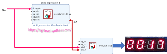
So the HLS code of the IP under measurement should provide start and end ports. Fortunately, this option is available in the Vitis-HLS using the block-level interface.
Let’s consider an IP that executes an arithmetic expression as a task. The following HLS code describes this IP.

Line 7 will add the block-level interface to the design, which contains start, done, idle, and ready signals. Here, we use start and done signals. The following figure shows these signals.

The latency measurement HLS code can be as follows.

This code uses a state machine to implement two states: idle state denoted by 0 and counting state represented by 1. It also detects the pulses on start and end inputs to switch between states. Finally, it returns the number of cycles between start and end signals.
After having these two IPs, we should connect them in a Vivado project. The following figure shows the Vivado design. The design consists of 9 IPs:
- The arithmetic_expression IP
- Latency measurement IP
- Debouncer: this IP receives a signal from a push button on the Basys3 board.
- Pulse generator: This IP generated a single clock cycle pulse to be used as the start signal
- Clocking wizard IP to generate a clock signal
- System reset IP
- Seven-segment timing signal generator
- Seven-segment driver IP
- And the system Integrated Logic Analyzer (ILA) IP to debug the design

After synthesising the Vivado project, we program the Basys3 board. Pressing the UP push button sends a start signal to the IPs. Then we can see the latency on the seven-segment, which is 17 in this case. The waveforms in the ILA window also confirm this value.


If you want to understand the HLS code behind all the IPs in the Vivado project, you can take my HLS course on Udemy. The links to these courses are available at this link.